Geometry of the bone present can make implant placement challenging. This can be especially true in the anterior, where the angle of the ridge requires a different trajectory than that of the prosthetic axis that will be used during restoration.1 Both the maxillary and mandibular ridge tip to the facial aspect, requiring implant placement that is not vertical in position. This can become more complicated in a site that is either edentulous or undergoing significant periodontal changes to the bone present, as the facial aspect is lost first, shifting the trajectory of the available bone present.
Periapical and panoramic radiographs only provide a 2D view of the 3D anatomy practitioners operate within. Therefore, information regarding the inclination of the triangle of bone is not available. Attempts at a flapless approach surgically in those cases can lead to perforation of the lingual plate or dehiscence on the facial aspect of the ridge. This implant placement requires a flapped approach to fully view the facial plate to aid in osteotomy preparation during implant placement.2, 3 Even under those circumstances, the surgeon must centre the drills in the space for the implant to be properly positioned in the mesiodistal orientation.4 This becomes more complex, with greater potential error, when placing two implants adjacent to each other and increases as more adjacent implants are planned. Angulation errors in the facio-lingual dimension can still occur with freehand placement, leading to prosthetic complications during the restorative phase.5
Simple surgical guides have been in use for a guided approach that is prosthetically driven.6 Those have ranged from guides created with denture teeth on the cast7 with guide holes to position the initial drills to metal sleeves8 that can, with appropriate inserts in the sleeve incorporated in the guide, allow guidance of each drill and implant insertion into the site. Unfortunately, those do not consider the 3D anatomy when fabricated and are created using a cast and viewing traditional radiographs to guide a hole drilled into that cast to position the sleeve and make the guide to that. Depending on the design of the guide and position in the arch, those may allow a flapless surgical approach or may still require a flap to verify orientation of the osteotomy in relation to the anatomy present. These factors can be challenging in a partially edentulous arch.9
Cone beam computed tomography (CBCT) has assisted in eliminating the lack of information provided by traditional radiographs by allowing analysis of the surgical area in 3D.10, 11 This technology has expanded on this improved information by permitting virtual planning of the implants and fabrication of CAD/CAM surgical stents to better guide the drills to create osteotomies that are anatomically and prosthetically guided. The benefit of this approach is that a flapless surgery can be performed if chosen during implant placement. Those guides are typically created by a laboratory after transmission of a virtually planned implant placement in CBCT using various software packages on the market. The laboratory then creates the surgical guide and returns it to the surgeon, and implant placement is performed.
Laboratory-fabricated surgical guides have some negatives to their use. Typically, there is the two- to three-week turnaround time between submission of the virtual planning and receipt of the CAD/CAM surgical guide. Additionally, there is a laboratory fee associated with that laboratory-fabricated guide. This may be cost prohibitive for the patient when a single implant is planned and adds to the treatment fee when multiple implants are planned in the same arch.
A simpler approach has been developed that uses a surgical guide fabricated in-office that does not require laboratory involvement. The guide is worn during a CBCT scan, and that data is imported into the implant planning software, where corrections to the planned trajectory and 3D position are made to the final in-office guide to be created. The result is a cost-effective surgical guide that can be quickly created in-office and that is guided based on the 3D anatomy, allowing a flap-free surgical approach that eliminates potential prosthetic complications if bone is adequate based on the desired implant position. A case demonstrating this technique and application with regard to adjacent implants to be placed, each requiring a different orientation with regard to the osseous anatomy, is presented.
Clinical case
A 76-year-old male patient presented with mobility and pain in the right mandible. Review of the medical history of the patient informed that he had controlled diabetes and high blood pressure, for which he was on medication with regular supervision by his physician. Examination noted that the mandibular right central incisor and lateral incisor had Grade II mobility and that the right canine presented with Grade III mobility.
Periapical radiographs were taken to access the conditions present (Figs. 1a & b). A large area of bone loss was noted around the entire root of the canine, which had no osseous support. The lateral incisor presented with 90% bone loss and the central incisor 75% bone loss. The patient was informed that, owing to the amount of bone loss, extraction of the three teeth was the recommended treatment that could be performed on those teeth.
Figs. 1a & b: Pretreatment radiograph demonstrating signicant bone loss associated with the mandibular right central incisor, lateral incisor and canine.
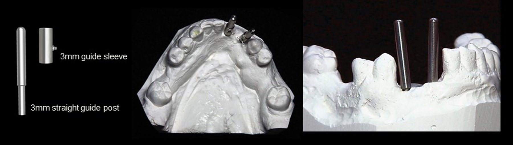
Fig. 2: A 3/32 in. drill was used to make a pilot hole in the edentulous area of the cast where implants were planned and guide posts inserted.
Treatment options to replace the teeth, which included a removable partial denture or placement of two implants and restoration with a three-unit fixed prosthesis, were discussed. The patient decided on the implant-retained fixed prosthesis as the treatment he wished to proceed with. Review of the steps necessary to follow this treatment option were discussed and the patient was informed that osseous grafting would be necessary at the time of extraction and, after a healing period, implants would be placed. The implants would then require a healing period to osseointegrate before restoration could be initiated. During the healing periods, the patient would wear a provisional partial denture. The patient was scheduled for surgery.
The patient presented, and informed consent forms were reviewed and signed by him. Local anaesthetic (4% articaine with 1:200,000 adrenaline) was administered in the buccal vestibule and lingual aspect for infiltration. The central incisor and lateral incisor and canine were extracted atraumatically with a forceps after detachment of the periodontal ligament with a periotome. The extraction sockets were curetted to remove any residual tissue related to the periodontal lesions present. In preparation for implant placement after site healing, osseous grafting was performed to create a bed to accommodate the planned implants. The material used was INFUSE Bone Graft (Medtronic), which contains a recombinant human bone morphogenetic protein-2, known to be upregulated in the bone healing process and thus assisting in bone regeneration. It stimulates the recruitment and differentiation of bone-forming cells, inducing new bone formation and healing existing bone. The solution was added to Puros (Zimmer Biomet Dental) and an absorbable collagen sponge. A resorbable non-ceramic bioactive bone graft was selected to aid in filling the sockets’ missing volume (OsteoGen, Impladent). These materials convert over time and are replaced with host bone. The grafting material mixture was placed into the extraction sockets and gently tamped down to eliminate any voids present between the grafting material and socket walls. The patient was dismissed and scheduled for a follow-up appointment to check site healing.
Figs. 3a & b: Guide sleeves were placed over the guide posts with the retentive cleats at the lingual aspect
At two weeks post-extraction and socket grafting, the patient presented and sutures were removed. The flap had healed uneventfully with primary closure. The patient was scheduled for an appointment at three months post-grafting to initiate the next phase of treatment. An impression was taken of the arch to fabricate the diagnostic guide. The impression was poured in stone to create a cast. A 3/32 in. drill was used in a laboratory handpiece to create a pilot hole in the cast at the estimated position and angulation at the central incisor and canine sites on the edentulous area, and guide posts (DePlaque) were inserted into the holes (Fig. 2). Owing to the different anatomical shapes of the two sites, the pilot holes were placed based on the cast’s anatomy and parallelism was not attempted. A guide sleeve (DePlaque) was placed over each of the two guide posts and the retentive cleats were positioned at the lingual aspect (Figs. 3a & b). Triad gel (Dentsply Sirona) was placed over the retentive cleats on the sleeves and over the lubricated surfaces of the adjacent teeth on the cast and lightpolymerised to create the diagnostic guide (Figs. 4a & b). A CBCT scan was taken with the diagnostic guide worn intra-orally. The data was imported into CS 3D implant planning software (Carestream Dental), and the position of the two sleeves were analysed with regard to orientation to the underlying ridge and its angulation.
A virtual implant was placed at each site in the software. It was determined that, based on the trajectory of the guide sleeves, that both implant sites were angled to the facial aspect. This would create lingual perforation when the osteotomies were prepared, and a correction would be necessary with the surgical guide that would be fabricated. Additionally, both planned implants would need to be shifted and angled lingually to allow the definitive restoration to have lingual access openings for the abutment screws. Analysis determined that the implant at the central incisor would need to be angled 9° to the lingual aspect and offset to the facial aspect at the crest by 1 mm and the canine angled 15° to the lingual aspect and offset to the facial aspect by 1 mm (Figs. 5a–c).
Figs. 4a & b: Triad gel was added to create a diagnostic stent that used the adjacent teeth for stability and locked to the guide sleeves’ cleats.
Figs. 5a–c: CBCT views showing orientation of the diagnostic guide sleeves in relation to the bone present (green line), indicating correction required on both planned sites to have implants placed within the arch. The red line indicates the angle correction, and the yellow line indicates the offset measurement to the facial and lingual aspects. The blue line indicates the newly planned axis of the implant.
Fig. 6: Guide Right Bending Tool and stylus.
Figs. 7a & b: A 1 mm offset post was bent to 9° for the central incisor site (a) and a 1 mm offset post was bent to 15° for the canine site (b).
Figs. 8a & b: Corrected 1.0 mm offset guide posts with 3.9 mm upper parts for alignment of 4.0 mm guide sleeves placed into the post holes on the cast.
Fig. 9: Guide sleeves were placed on the upper removable parts of the corrected guide posts.
Fig. 10: The cleats on the guide sleeves were orientated to maximise retention in the resin to be placed to fabricate the surgical guide.
11: Triad gel was placed, completing the corrected Guide Right surgical guide.
Figs. 12a & b: The corrected Guide Right surgical guide was tried into the mouth to verify t and stability (a). A 2.3 mm insert and a 3.0–4.0 mm insert were placed in the 4.0 mm guide sleeve before the 2.2 mm drill was used to start the osteotomy (b).
The corrections to the guide posts would be made using the Guide Right Bending Tool (DePlaque; Fig. 6) and the appropriate offset guide posts. As planned in the virtual software, for the central incisor site, a 1 mm offset post (DePlaque) was bent using the bending tool previously mentioned to achieve the desired 9° correction to the pilot hole in the cast (Fig. 7a). This was repeated for the canine site using a 1 mm offset post which was bent to 15° (Fig. 7b). The corrected offset guide posts were inserted into the cast at the appropriate pilot holes, and 3.9 mm upper removable parts were placed over the top portion of the offset guide posts (Figs. 8a & b). Guide sleeves (4 mm) were placed over the upper removable parts with the cleats at the lingual aspect and oriented to maximise resin retention to them (Figs. 9 & 10) Triad gel was flowed over the cleats and adjacent lubricated portions of the cast and light-polymerised to create the corrected surgical guide (Fig. 11).
The surgical stent was soaked in povidone-iodine prior to use surgically. Chlorhexidine may be used as an alternative liquid to disinfect the guide. Local anaesthetic was administered, and the surgical guide verified for fit and stability intra-orally (Figs. 12a & b). A crestal incision was made with a scalpel, and a full-thickness flap was reflected to expose the crest. The Guide Right surgical guide with 4 mm guide sleeves was inserted. The osteotomies were initiated with a 2.2 mm drill in a 2.3 mm insert and completed with Densah osseodensification burs (Versah), starting at 2.5 mm and continuing to 3.5 mm in diameter to a depth of 11.5 mm at both sites through the surgical guide (Fig. 13). A 3.5 × 11.5 mm implant was placed into the central incisor site and a 4.0 × 11.5 mm implant was inserted into the canine site (AnyRidge, MegaGen). A post-insertion radiograph was taken (Fig. 14a). Cover screws were placed on both implants, and the flap was secured with sutures.
Owing to the pandemic and shutdown, a delay in the return of the patient to initiate the prosthetic stage of treatment resulted. When the patient returned, the implants were exposed with a split-thickness flap. An implant stability quotient value of 80 was recorded for the central incisor implant and of 84 for the canine implant, and healing abutments were placed. A radiograph was taken to check the status of the implants (Fig. 14b). An open-tray impression was captured, opposing impressions taken and a maxillomandibular relationship record taken. Healing abutments were replaced, and the impressions were sent to the laboratory for fabrication of the prosthesis.
Fig. 13: Densah osseodensication drills used through the Guide Right surgical guide to create the osteotomies for the implants to be placed.
Figs. 14a & b: Periapical radiographs of the implant placement (a) and healing abutments placed (b).
Figs. 15a & b: Radiograph of the denitive restoration (a) and the denitive restoration displaying the lingual access openings (b).
Figs. 16a & b: Completed prosthesis with a three-unit screw-retained bridge on the implants, labial (a) and palatal (b) view.
Two weeks later, the laboratory work was returned, and the patient presented for insertion. The healing abutments were removed, and the screw-retained three-unit bridge was tried in, and the fixation screws hand-tightened. A periapical radiograph was taken to verify mating of the prosthesis to the implants (Figs. 15a & b). The screws were tightened with a torque wrench to the manufacturer’s recommended torque, and the screw access channels sealed with PTFE tape and flowable composite (Figs. 16a & b). The occlusion was checked, and no adjustment was indicated.
Conclusion
Implant placement can be challenging owing to the position and angulation of the available bone present. This is particularly true in the anterior maxilla and in the case of poor placement, especially when surgery is performed in a flapless manner. Poor placement can result in insufficient bone on the facial aspect of the implant, leading to eventual failure, as occurred with the initial implant the patient presented with. Evaluation of available bone is difficult with traditional 2D radiographs, as the facio-lingual dimension is lost for evaluation and can only be assessed with a CBCT scan. Software is then able to allow virtual planning and fabrication of a surgical guide to replicate placement based on the anatomy present and virtual positioning. A simplified process using the Guide Right system permits in-office fabrication of a simple guide that is used as a diagnostic guide worn during the CBCT scan and permits references during virtual planning and then fabrication of a corrected surgical guide, thus reducing both the cost of the surgical guide and the time required to have the guide ready for the implant placement appointment—an ideal option in the partially edentulous arch.
Implant planning and placement in the completely edentulous maxilla can present challenges both surgically and prosthetically whether a removable or fixed ...
Prosthetically driven implant placement has become a fundamental principle in contemporary implant dentistry, particularly in the treatment of edentulous ...
Having used DrQuickLook SD for some time now, I see how its range gets larger each and every day. By that I mean I find more and more uses for it. I can ...
Israeli-based company A.B. Dental has developed a new service for customized implants that combines the latest technologies in implantology, digital ...
Glidewell has announced the national launch of an innovative new approach to implant dentistry. The Glidewell HT No-Charge Implant Program is designed to ...
BIBERACH AN DER RISS, Germany: As the use of CBCT imaging in dentistry has become more commonplace, its sophistication as a diagnostic tool likewise has ...
As cone-beam computed tomography (CBCT) becomes more prevalent in the dental field, various legal issues are coming to light. When CBCT scans are justified,...
Learn surgical guide design in Blue Sky Bio Plan and surgical guidance for full arch. This course is for dental professionals with an advanced understanding...
Surgical guides have transformed implant placement for millions of cases — and they have been an excellent tool. But guides are built on a pre-operative ...
CHICAGO, US: The American Dental Association (ADA) has called on US insurance regulators to scrutinise a new Delta Dental of California policy under which, ...
NEW YORK, US: Reduced salivary flow is a well-recognised feature of Down’s syndrome and is thought to contribute to the high prevalence of periodontal ...
BREA, Calif., US: Pac-Dent, a provider of digital dentistry materials and workflow solutions, has announced the expansion of its Rodin ecosystem with the ...

 International / International
 Brazil / Brasil
 Canada / Canada
 Latin America / Latinoamérica
 Austria / Österreich
 Bosnia and Herzegovina / Босна и Херцеговина
 Bulgaria / България
 Croatia / Hrvatska
 Czech Republic & Slovakia / Česká republika & Slovensko
 France / France
 Germany / Deutschland
 Greece / ΕΛΛΑΔΑ
 Hungary / Hungary
 Italy / Italia
 Netherlands / Nederland
 Nordic / Nordic
 Poland / Polska
 Portugal / Portugal
 Romania & Moldova / România & Moldova
 Slovenia / Slovenija
 Serbia & Montenegro / Србија и Црна Гора
 Spain / España
 Switzerland / Schweiz
 Turkey / Türkiye
 UK & Ireland / UK & Ireland
 China / 中国
 India / भारत गणराज्य
 Pakistan / Pākistān
 Vietnam / Việt Nam
 ASEAN / ASEAN
 Israel / מְדִינַת יִשְׂרָאֵל
 Algeria, Morocco & Tunisia / الجزائر والمغرب وتونس
 Middle East / Middle East

 Dr. Cameron Shahbazian DMD MBARegister now1CELive webinar
 Dr. Bruce McFarlane Certified Specialist in Orthodontics Fellow: Royal College of Dentists of Canada Diplomate: American Board of OrthodonticsLive webinar


 Prof. Dr. Wael Att, Dr. Andrea Laureti ITI Scholar Michigan, Dr. Acela MartinezLive webinar
 Cat EdneyRegister now1CE


, indicating correction required on both planned sites to have implants placed within the arch. The red line indicates the angle correction, and the yellow line indicates the offset measurement to the facial and lingual aspects. The blue line indicates the newly planned axis of the implant.")

 and a 1 mm offset post was bent to 15° for the canine site (b).")


. A 2.3 mm insert and a 3.0–4.0 mm insert were placed in the 4.0 mm guide sleeve before the 2.2 mm drill was used to start the osteotomy (b).")

 and healing abutments placed (b).")
 and the denitive restoration displaying the lingual access openings (b).")
 and palatal (b) view.")

 and healing abutments placed (b).")
 and the denitive restoration displaying the lingual access openings (b).")
 and palatal (b) view.")


To post a reply please login or register