Search Dental Tribune

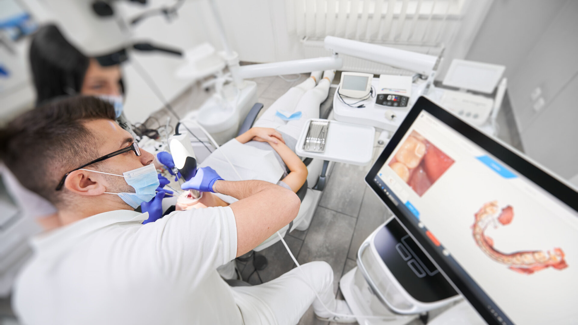
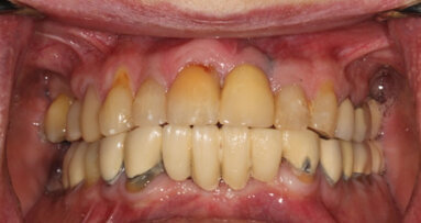
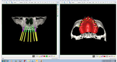
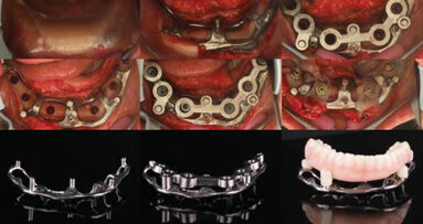
Intra-oral scanners play a vital role in modern full-arch implant restoration. (Image: anatoliy_gleb/Shutterstock; clinical images: Isaac D. Tawil, Scott D. Ganz)

Full-arch implant-supported reconstruction continues to provide viable solutions to restore and improve function, enhance aesthetics and change quality of life for our patients. All-on-X implant reconstruction has benefited from new advancements and technical innovations. In this article, we continue the journey of navigating through new developments that impact full-arch analogue and digital workflows.

Our previous articles introduced several elements to aid the clinician in both the surgical and restorative phases of full-arch replacement, including the use of CBCT-guided surgical apps1 and how CBCT has greatly improved the assessment for implant placement relative to the desired restorative position for provisional and final restorations while reducing implant complications.

We have previously described an ancillary surgical protocol utilising extracted teeth as an autologous solution for bone grafting, which has greatly enhanced healing and long-term alveolar stability, providing ample graft volume while significantly reducing biomaterial costs.2 Subsequent publications also reported on improving the restorative time and treatment outcome utilising iJIG technology3 and employing small hole technology (C2F) to enhance the physical integrity and anatomy of milled or 3D-printed provisional restorations4 and to improve inter-arch alignment and occlusion.

The goal of these articles was to improve time, efficiency, costs and long-term results for the benefit of clinicians, laboratory technicians and patients. This latest article endeavours to provide updates on the acquisition of data necessary to complete the restorations and addresses improvements in full-arch screw-retained monolithic restorations which incorporate multi-unit abutments (MUAs).

Data acquisition

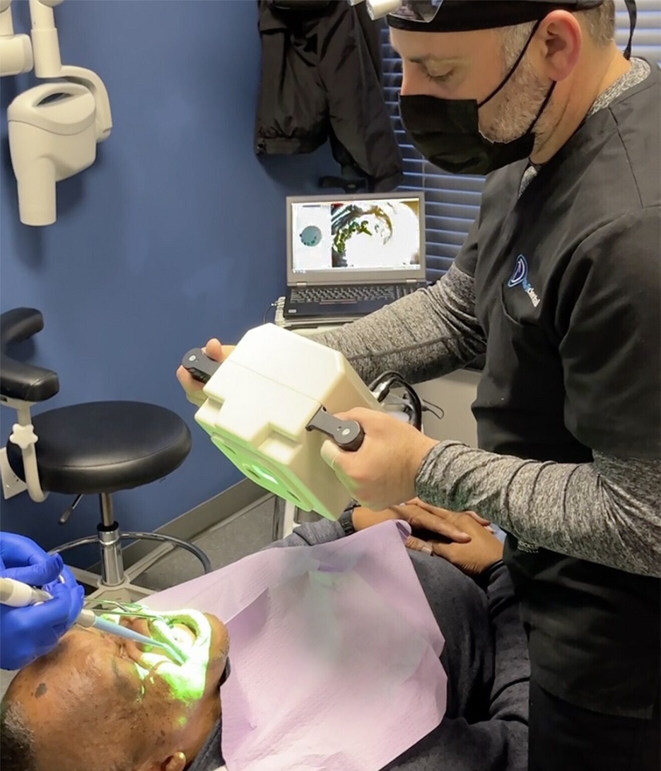
As the dental industry continues to strive for fully digital solutions, the development and improvement of intra-oral data devices and acquisition technology has continued to evolve. Intra-oral scanning (IOS) speeds and accuracies have made intra-oral scanners a viable replacement for direct analogue impressions. Native IOS software apps now provide several impressive features which enhance and streamline complete digital protocols. However, owing to inherent logistical limitations, using IOS technology for full-arch dental implant restorations has presented difficulties and inaccuracies, requiring additional apps to achieve fully digital solutions.

All-on-X surgical and restorative protocols require the placement of four or more implants with a favourable anterior–posterior spread to achieve the necessary long-term support. Capturing the positions of these implants with accurate cross-arch IOS, especially in the mandible, has been one of the major struggles for clinicians and dental laboratory technicians to overcome.

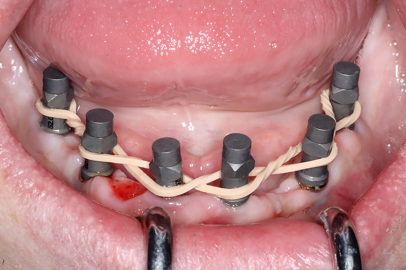
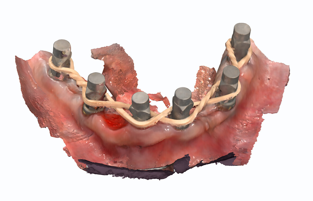
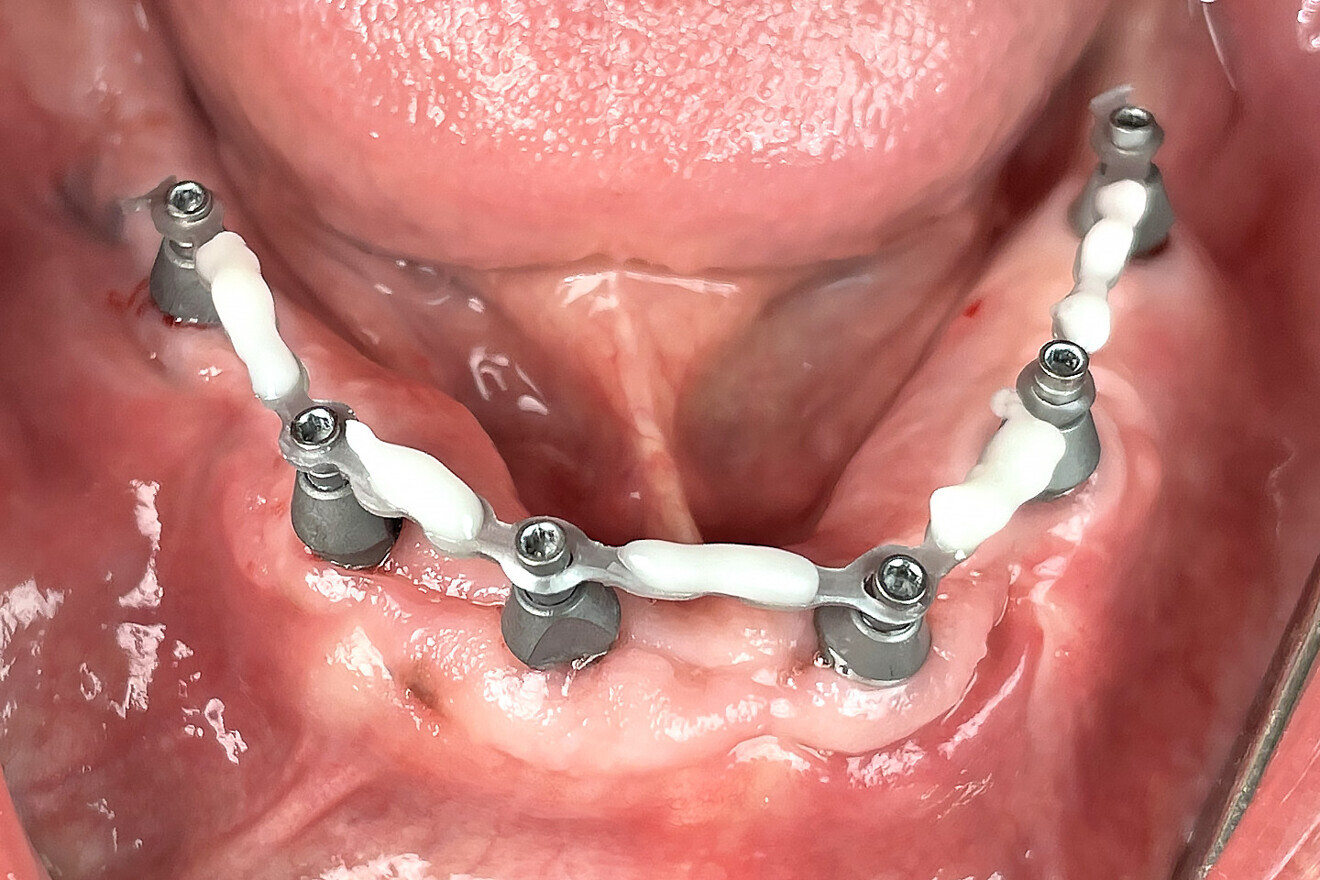
IOS technology requires a stable environment for data to be stitched and captured accurately. Several techniques have emerged to aid the clinician in scanning these difficult environments, characterised by improper retraction, salivary flow, lack of stable keratinised soft tissue and large distances between scanned objects. The splinting of scan bodies with elastic bands or wires (Figs. 1a & b), for example, has facilitated the ability of scanners to continue a scan without interruption by creating a linear path for data capture.5 Innovative techniques such as the sigma composite curve (Fig. 1c) and fiducial markers fixated to the bone have also helped improve the scanning flow.6 While these processes work for some and not for others, developers have created alternative workflows to aid in the acquisition of accurate intra-oral data.

Figs. 1a–c: Rubber bands (a & b) or composite applied directly to the tissue (c) to aid intra-oral scanners in acquiring accurate data.

Figs. 1a–c: Rubber bands (a & b) or composite applied directly to the tissue (c) to aid intra-oral scanners in acquiring accurate data.

Fig. 1b

Fig. 1b

Fig. 1c

Fig. 1c

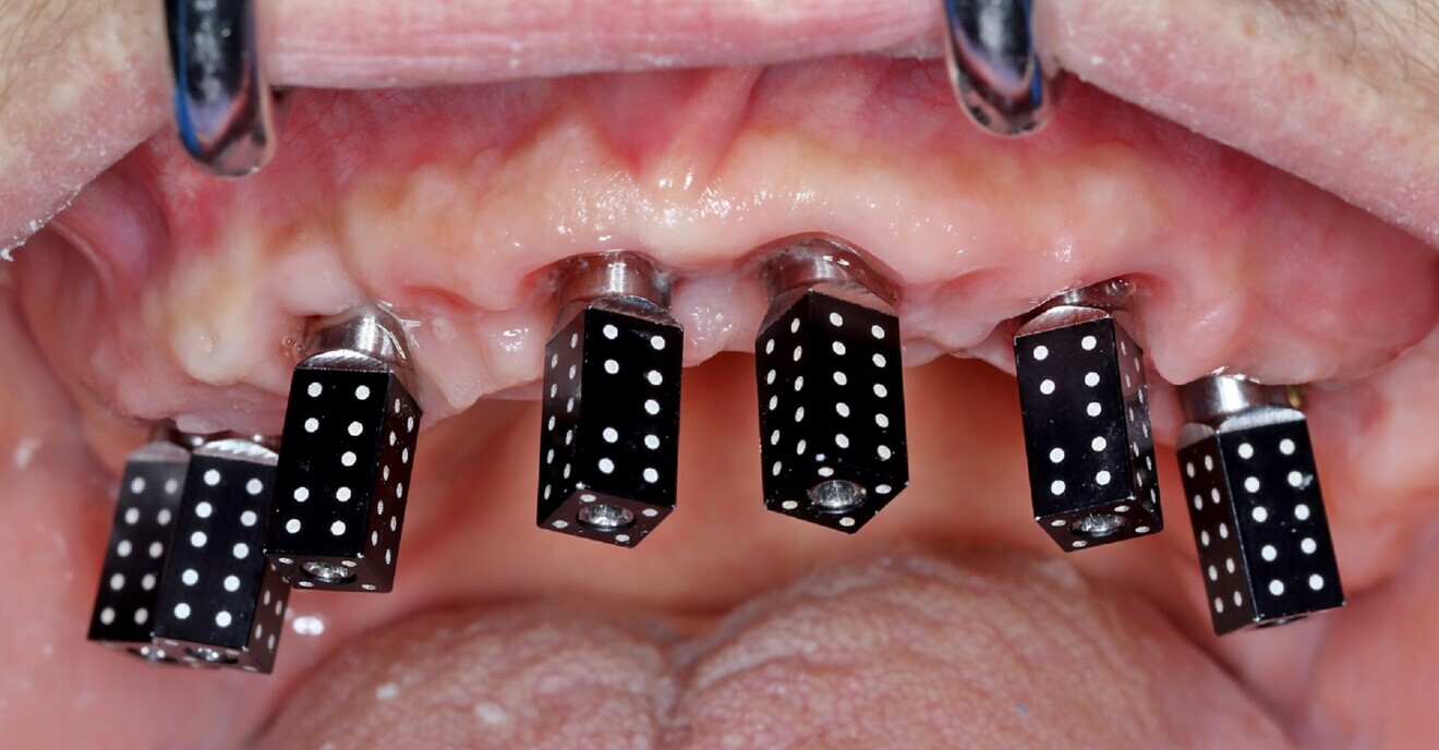
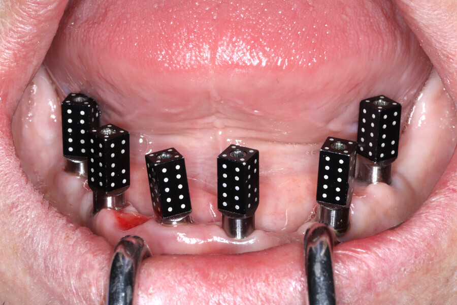
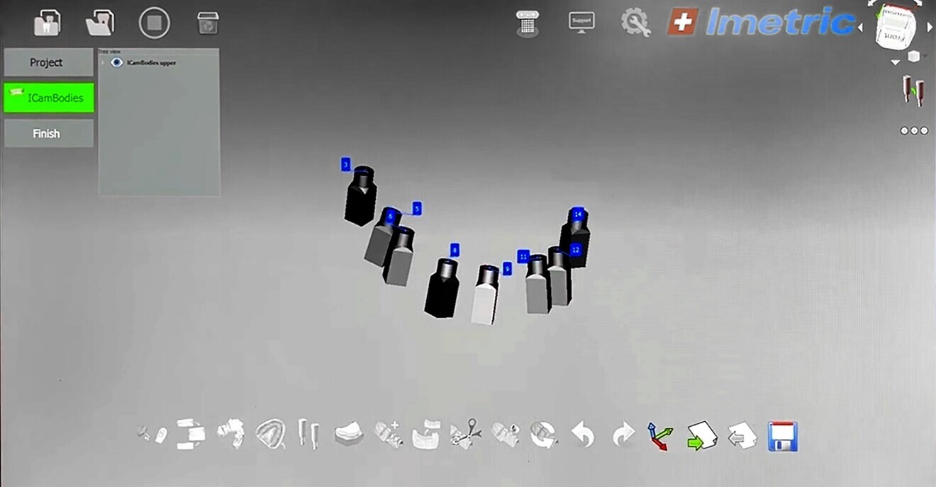
Photogrammetry in dentistry is a relatively new development that has revolutionised capture and positional analysis.7 Photogrammetry is a diagnostic and research method that uses an extra-oral capture device with specific photogrammetry scan bodies to acquire measurements from 2D digital images (Figs. 2a & b). Photogrammetry scans allow dental clinicians to acquire precise measurements of the individual scan bodies (Fig. 2c) secured to the dental implants either at the time of surgical placement or after the implants have been uncovered.8 While extremely accurate for recording the  positioning of the implants, photogrammetry does not acquire the topography of the soft tissue. Therefore, a second scan is required with an intra-oral scanner. The IOS data can then be used to fabricate a virtual 3D model used to measure various parameters of the implant analogues.9 The software correlation of these measurements can be used to assess and validate the correct positioning of implants and the alignment of the patient’s occlusion, regarding tooth size, distance and angle.

Fig. 2a: Photogrammetry. Manufacturer-specific scan bodies.

Fig. 2a: Photogrammetry. Manufacturer-specific scan bodies.

Fig. 2b: Photogrammetry. Extra-oral light source (iCam4D).

Fig. 2b: Photogrammetry. Extra-oral light source (iCam4D).

Fig. 2c: Photogrammetry software (iMetric 4D).

Fig. 2c: Photogrammetry software (iMetric 4D).

The combination of IOS and photogrammetry data provides the CAD software with all the necessary information to virtually create a provisional prosthesis or a final restoration to be 3D-printed or milled. The advanced capability of this highly accurate technology generates a fully digital workflow. There is little need for an analogue model for production or verification purposes. Although these impressive devices are extremely accurate, the initial purchase costs and availability of sensitive component materials has been an issue of concern.

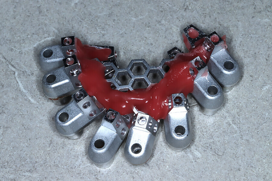
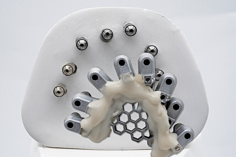
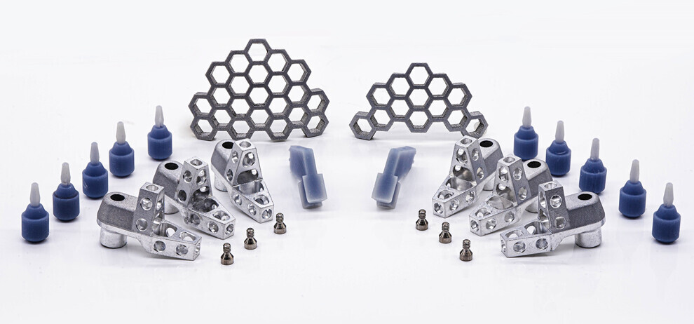
Fig. 3a: Grammetry components for splinting for increased accuracy and stability.

Fig. 3a: Grammetry components for splinting for increased accuracy and stability.

To obviate the expense of photogrammetry, alternative fully digital workflows have been developed, such as Dr Jonathan Abenaim’s XCell process to facilitate and streamline data acquisitions, avoiding the need for photogrammetry.10 This proprietary workflow protocol requires education therein and the use of proprietary scan bodies. To maintain consistency and accuracy, the protocol recommends a specific intra-oral scanner and CAM unit. Additionally, the workflow recommends use of Dr Abenaim’s Powerball screw to complete the production of the final restoration. Although the recommendations are not mandatory, there is limited support when not utilising the components indicated. The proven XCell process is extremely efficient and paved the way for continued development of other intra-oral imaging technology.

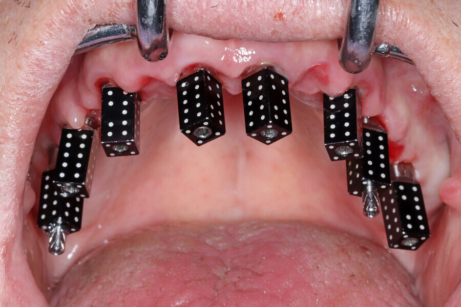
Another very recent option, called Grammetry (ROE Dental Laboratory), has been developed as an open comprehensive surgical and restorative solution that offers a very similar and straightforward process at a significantly reduced cost. Whereas photogrammetry requires the use of an expensive device and expensive scan bodies, Grammetry allows the use of the dentist’s existing intra-oral scanner along with special components provided to the clinician for each case.

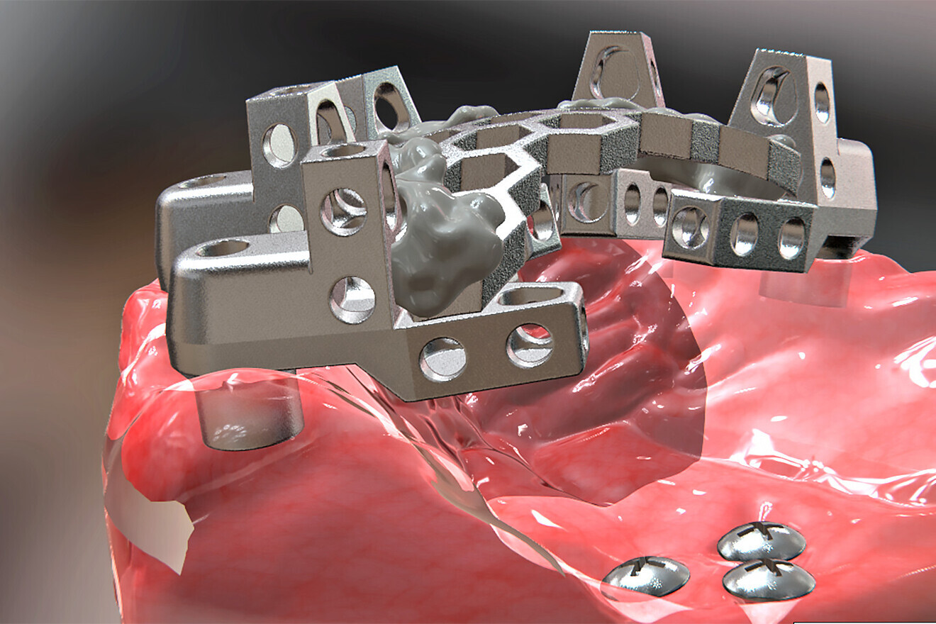
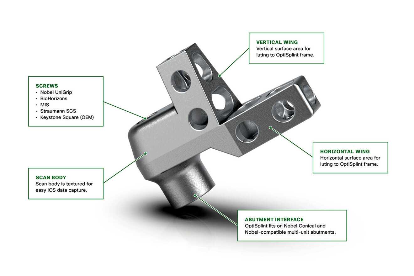
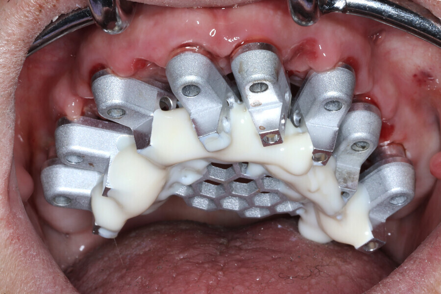
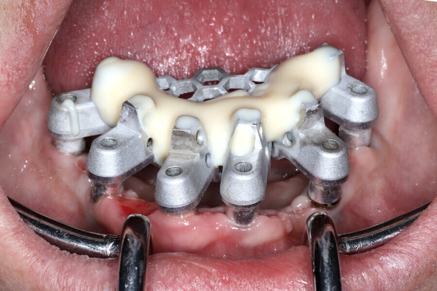
The analogue–digital process utilises MUA-compatible scan bodies (OptiSplint) designed to incorporate an aluminium mesh frame (Fig. 3a) that can be customised chairside (with the snipping tool included) as required by the intra-oral location of the implants. This mesh frame comes in small and large sizes to accommodate various mouth sizes and MUA–implant positions. The workflow involves inserting the scan bodies on to the MUAs intra-orally (Fig. 3b). The proprietary scan bodies have extensions (Fig. 4) to allow the mesh to seat and rotate in close proximity to the extensions, which facilitate luting using a resin base material (STELLAR DC Acrylic, Taub Products). The structure can then be digitised by scanning intra-orally with an intra-oral scanner and extra-orally with an intra-oral scanner or desktop scanner. The bonded splinting of the scan bodies to the mesh frame allows for a simple uninterrupted scan path.

Fig. 3b: Completed Grammetry intra-oral structure secured to MUAs with conventional screws.

Fig. 3b: Completed Grammetry intra-oral structure secured to MUAs with conventional screws.

Fig. 4: Grammetry scan body with vertical and horizontal extensions to aid in bonding to the mesh frame. IOS = intra-oral scanning; OEM = original equipment manufacturer.

Fig. 4: Grammetry scan body with vertical and horizontal extensions to aid in bonding to the mesh frame. IOS = intra-oral scanning; OEM = original equipment manufacturer.

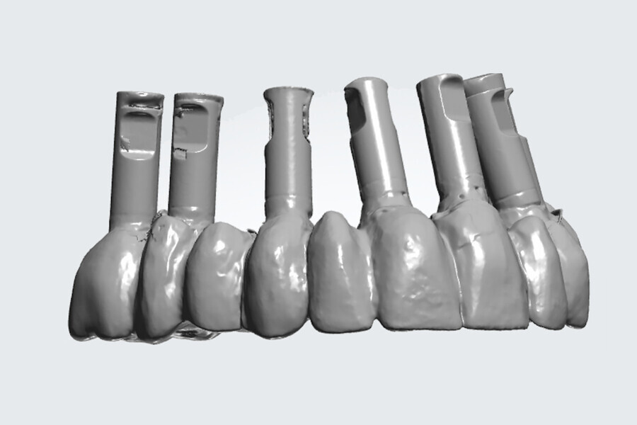
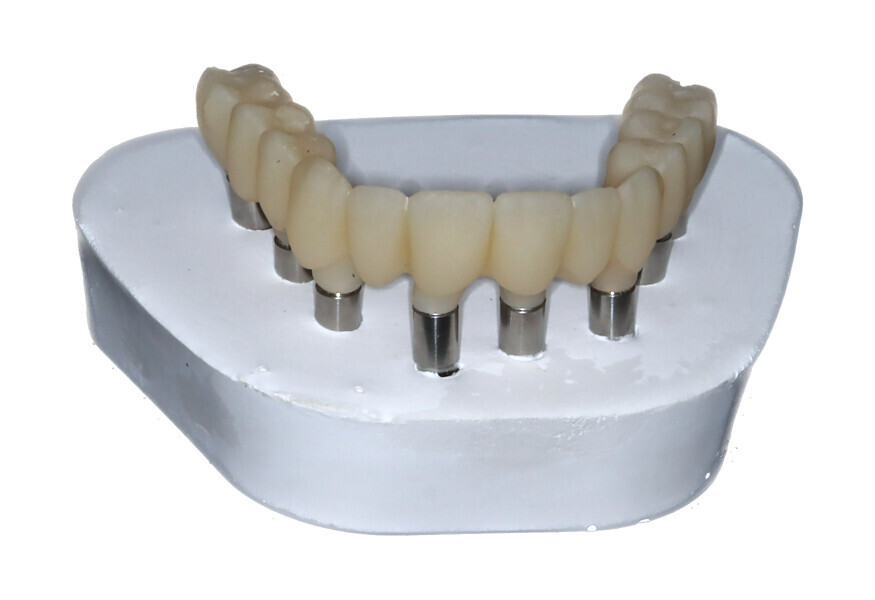
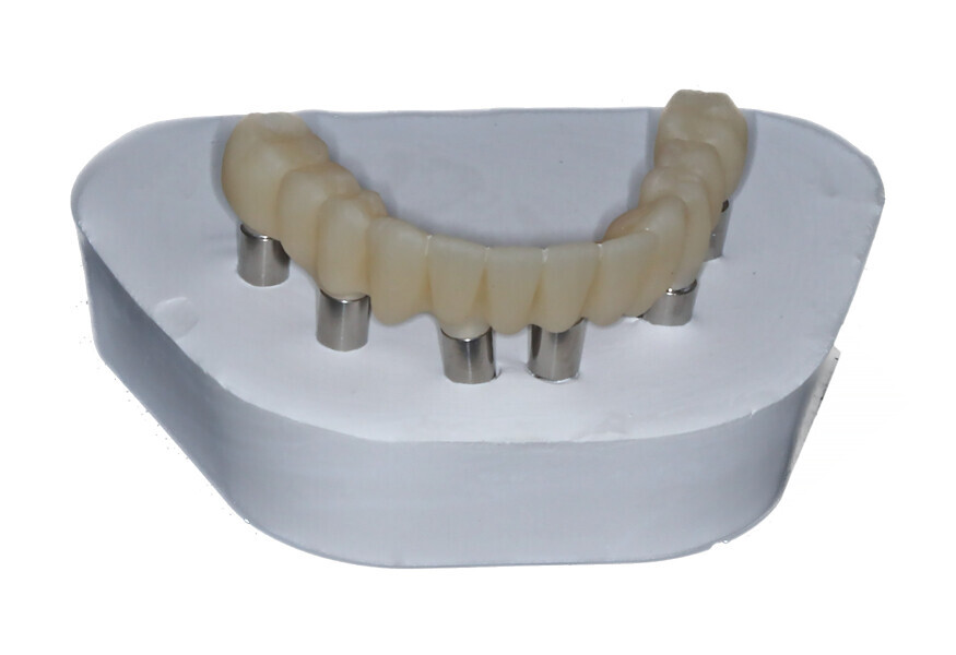
The Grammetry process provides the clinician with the fully digital benefits of photogrammetry while providing the capability to fabricate analogue models that can be articulated as part of the prosthetic design process represented by the clinical workflow (Fig. 5). Additionally, the Grammetry splint can be used as a model verification jig. The fully digital Grammetry process communicates to the dental laboratory the necessary records workflow to design and fabricate a full-arch prosthesis at a significantly reduced cost. For those who have 3D printers and wish to design and print the provisional prosthesis, a calibration device is included in the Grammetry kit. This device will ensure that the specific printer settings based on the resin used will achieve a passive fit.

Ti base or not Ti base? That is the question

The desire for screw retention over cementation for fixed prostheses has been debated for some time.11 As restorative components have evolved and CAM software and hardware capabilities have improved dramatically, screw retention utilising MUAs has become the preferred choice for most full-arch restorations owing to the passivity required for monolithic zirconia prostheses. The success of full-arch screw-retained cross-splinted restorations can be attributed to the elimination of subgingival cement and the passivity of prosthesis seating.12

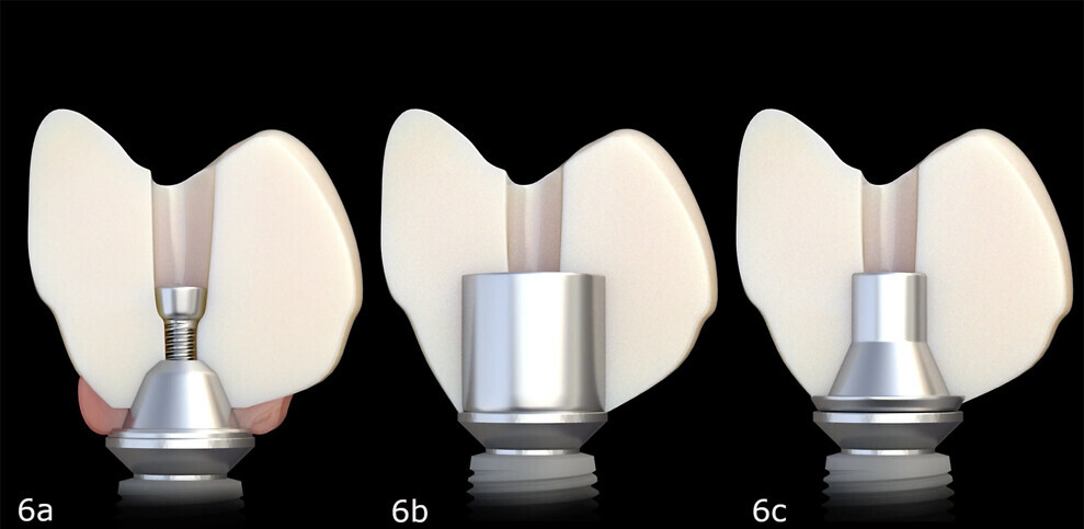
Figs. 6a–c: Three methods of attaching zirconia restorations to implants. Conventional multi-unit abutment (a). Titanium bar (b). Titanium base (c).

Figs. 6a–c: Three methods of attaching zirconia restorations to implants. Conventional multi-unit abutment (a). Titanium bar (b). Titanium base (c).

Screw-retained fixed implant prostheses have undergone many iterations over the past several decades.13 PMMA denture conversions proved too weak to withstand occlusal forces long term. To improve strength, metal frame reinforcement was added to the acrylic, but the end results still yielded a high level of long-term prosthetic failures. Improvements in metal–ceramic restorations yielded improved long-term aesthetics and longevity; however, the associated costs became a factor and fractures continued to occur. Owing to the improving strength and diversity of materials and the continued development of CAD/CAM technology, other material choices have become more viable. Monolithic zirconia has become the most widely used material for full-arch implant-supported restorations.14, 15 The milled and sintered zirconia structure can be fabricated with a standard MUA coping, a custom-milled titanium bar or a titanium base (Fig. 6).

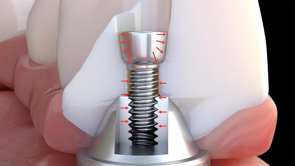
These metal substructures are chemically luted to the zirconia structure. Initially, while costs were significantly reduced, fractures were still evident, most notably from poor design. The fractures tended to occur in distal extensions, attributed to poor anterior–posterior spread, and in locations of screw access holes. Screw access fractures can be attributed to insufficient zirconia thickness at the crown–abutment interface. Conventional prosthesis-retaining screws secured to MUAs have a screw head that is 2.00 mm in diameter, only allowing for 0.25 mm of screw surface to engage the crown portion (Fig. 7). This leaves only 0.4 mm between the head of a conventional screw and the titanium base. Screw loosening, screw fracture and debonding of titanium bases from the zirconia structure have become a source of difficulty and concern.16 As these complications and avoidable remakes continue to persist, developers have searched for alternative solutions.

Figs. 7a–c: Dimensions of a standard multi-unit abutment screw head and the available zirconia (a & b), leading to fracture (c).

Figs. 7a–c: Dimensions of a standard multi-unit abutment screw head and the available zirconia (a & b), leading to fracture (c).

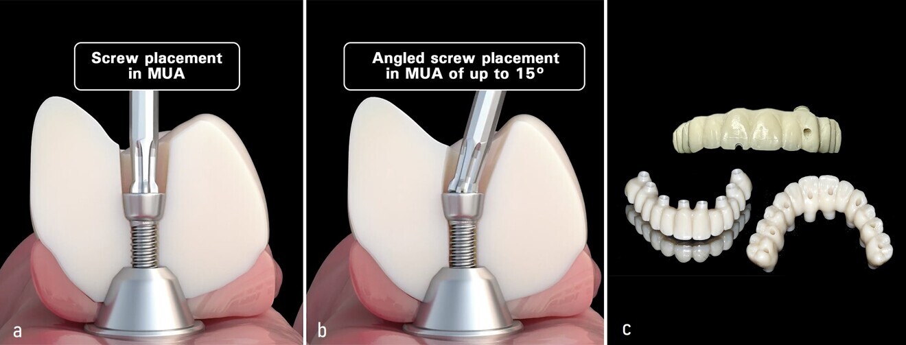
Figs. 8a–c: Straight screw access hole (a). Angled screw access hole of up to 15° (b). Straight vs angled screw access holes and variation in access hole positions for improved strength and aesthetics in multi-unit abutments (c).

Figs. 8a–c: Straight screw access hole (a). Angled screw access hole of up to 15° (b). Straight vs angled screw access holes and variation in access hole positions for improved strength and aesthetics in multi-unit abutments (c).

To counter the effects of screw loosing, titanium base debonding and screw access hole fracture, several new screws have been developed. Over the past few years, the continued refinement of these screws has led to the evolution of metal-free full-arch monolithic zirconia restorations. As a result, in many cases, the need for excessive bone reduction to accommodate the metallic portion has been eliminated, allowing for increased potential for Misch classification FP-1 compared with FP-3 restorations.17 Some of these screws allow for increased thickness of zirconia between the MUA and screw head. Allowing increased thickness in this susceptible region further reduces the risks of zirconia fracture of the area of the screw access hole. Additionally, the newer screws typically have a tapered or rounded screw head, allowing for improved retention by applying pressure to the lateral walls in the apical direction, reducing incidences of screw loosening.

Fig. 9: Grammetry Vortex LA VIS screw attached directly to the multi-unit abutment, allowing for increased thickness of zirconia dependent on the available interocclusal space. (Image: Danny Domingue)

Fig. 9: Grammetry Vortex LA VIS screw attached directly to the multi-unit abutment, allowing for increased thickness of zirconia dependent on the available interocclusal space. (Image: Danny Domingue)

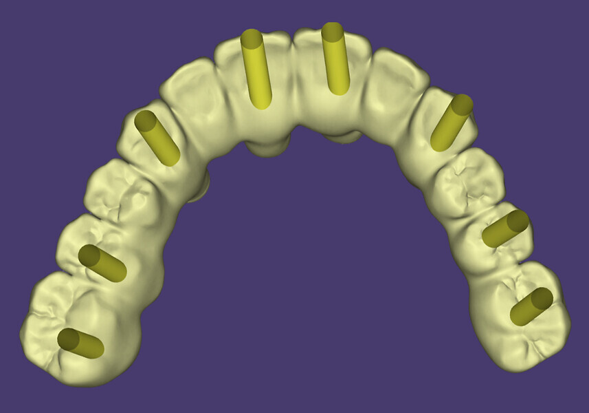
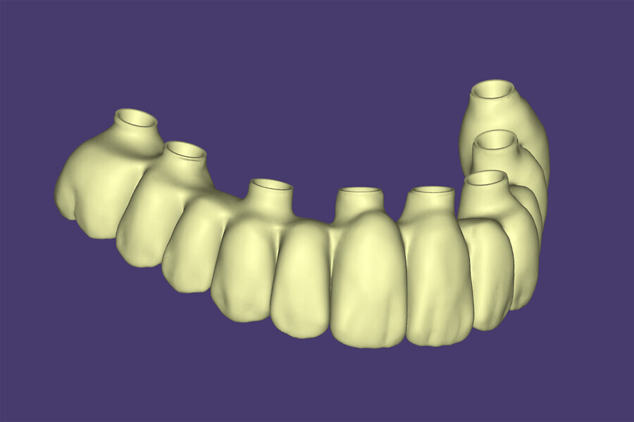
A few of these newer screw designs can accommodate angled screw access holes. Angled screw access hole correction has become widely incorporated in single-tooth implant restorations.18 Previously, correcting angulations for full-arch restorations on MUAs required using an MUA with an increased degree of angulation. When an MUA is secured to the implant and the scan data has been captured, altering the screw access hole requires removing and replacing the MUA with one with an increased angle. This becomes problematic when provisional or final restorations have already been designed, and a positional tooth change is requested. Often, these changes can leave access holes in aesthetic or potentially vulnerable areas (Fig. 8).

Additionally, there are angular limitations of MUAs, varying according to each component manufacturer. Rather than changing the MUA and dealing with the difficulties of temporisation, some of the newer MUA screw technologies allow for the MUA to remain in place and for angulation of the screw access hole to as much as 25°. One screw in particular that is uniquely designed in this regard is the Grammetry Vortex LA VIS screw (Fig. 9). This screw can accommodate various vertical positional depths. This feature allows for accommodation directly on the MUA, titanium base or titanium bar simply by adjusting the height position of the screw. The adjustable vertical position allows for more or less zirconia if desired, depending on the available interocclusal space. In addition to accommodating angled screw access holes, the ideal screw access position and depth can be achieved.

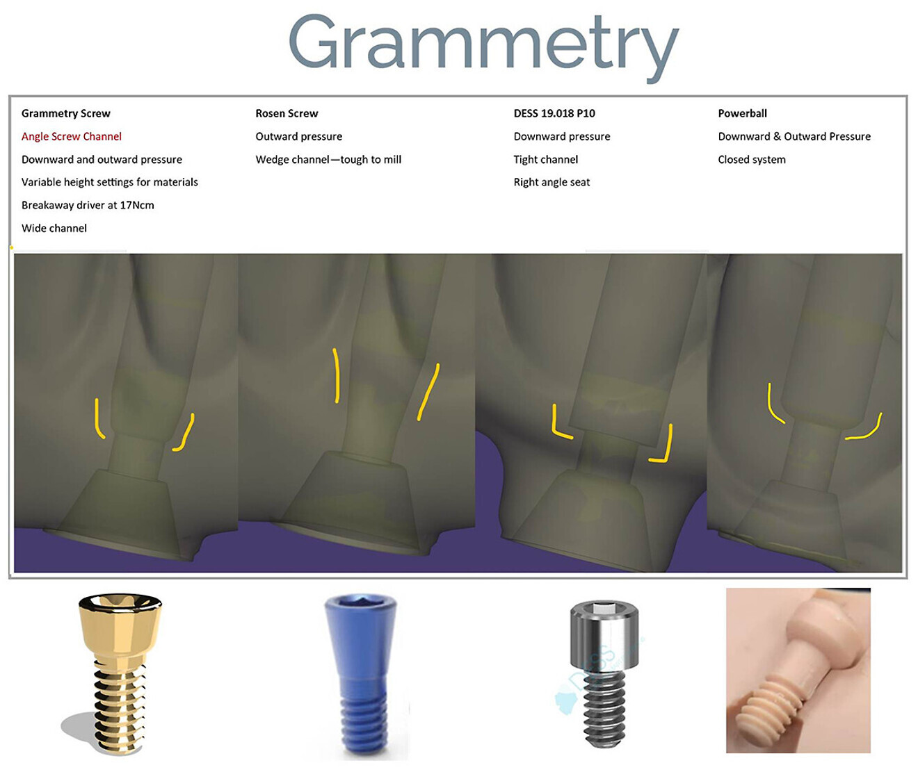
Therefore, utilising the innovative methods of data capture and validation described in this article combined with the newer screw technology, it is possible to accomplish increased efficiency and accuracy of the fabrication process. Additionally, it has been illustrated that screws which can accommodate an angled screw access hole will result in improved aesthetics (Fig. 10).

Fig. 10: New and innovative screw technology features and benefits with design and torque information.

Fig. 10: New and innovative screw technology features and benefits with design and torque information.

Case presentation

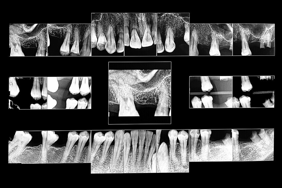
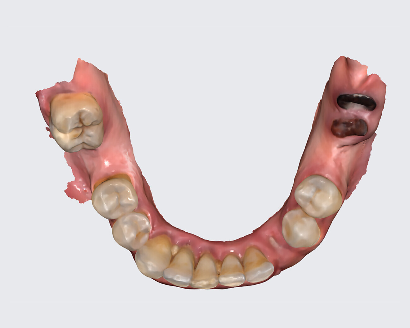
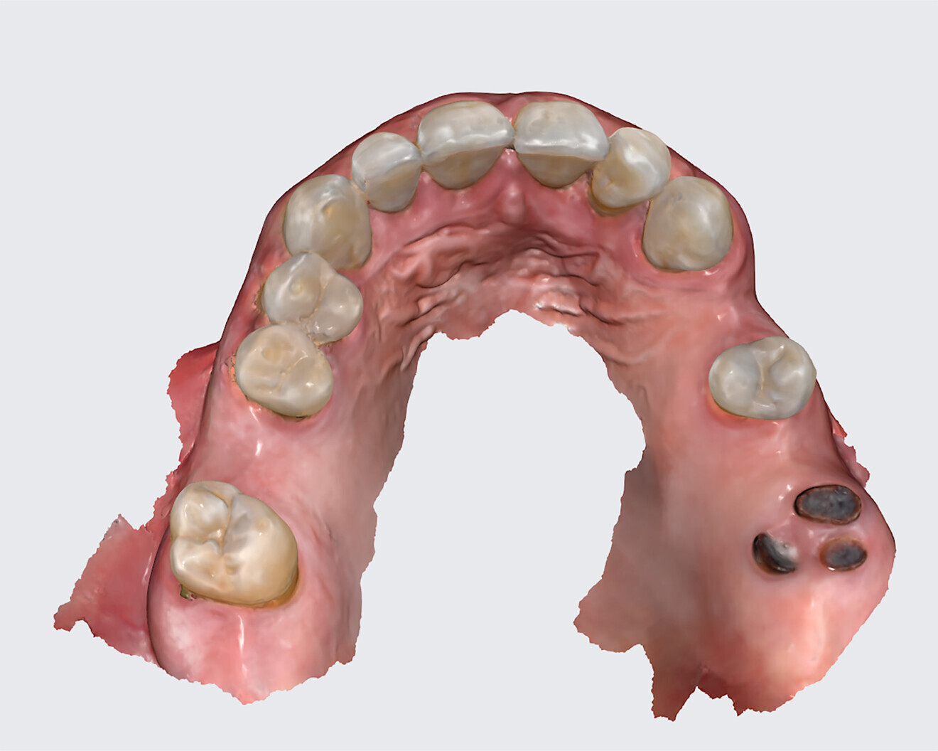
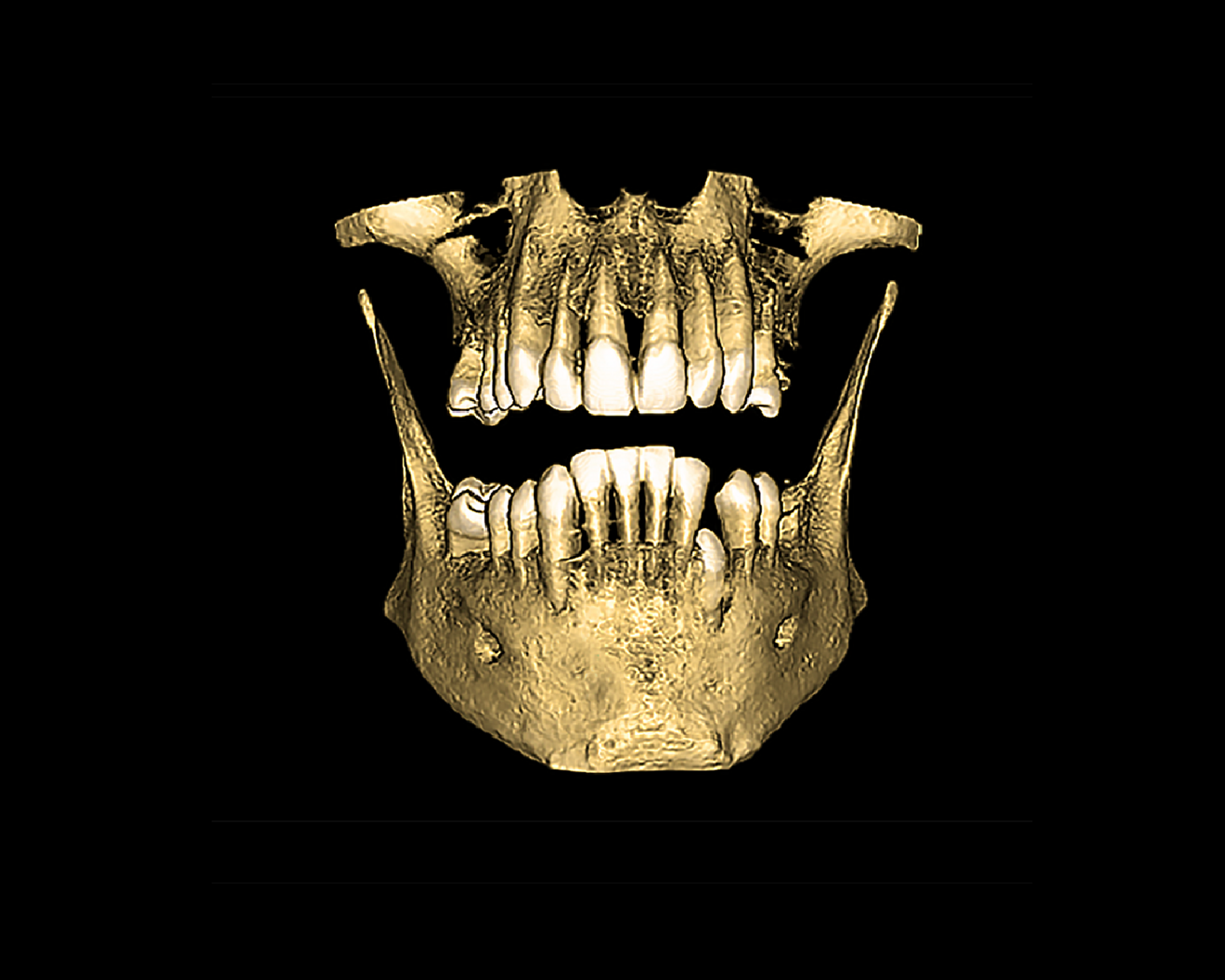
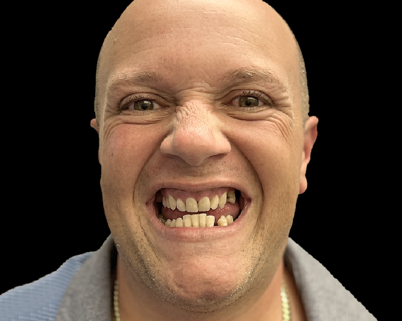
The following case exhibits the features and benefits of utilising Grammetry in combination with innovative screw technology. The 63-year-old male patient with a non-contributory medical history presented with failing dentition in both arches. Diagnostic records were collected, including full-mouth digital radiographs (RVG 6200, Carestream Dental; Fig. 11a), intra-oral scans (Medit i700 wireless; Figs. 11b & c), a large field of view CBCT scan (Carestream 9600; Fig. 11d), and intra-oral and extra-oral photographs (Fig. 11e). The mandible contained an impacted canine as well as several mobile and painful teeth. The maxilla was in a similar condition, having deteriorating, painfully mobile teeth, as well as extensive caries. While the bone loss was significant in the mandible, the vertical dimension of occlusion (VDO) allowed for both arches to be treated with an FP-1 prosthesis.

Fig. 11a: Full-mouth radiograph series revealing caries and periodontal defects.

Fig. 11a: Full-mouth radiograph series revealing caries and periodontal defects.

Based on the assessment of the acquired data, several treatment plans were developed and presented to the patient. Treatment concepts that were considered included salvaging those teeth deemed stable enough to be utilised to retain removable restorations, implant stabilisation with a combination of fixed and removable prostheses, implant-supported overdentures and full-mouth reconstruction with implant therapy. After reviewing the various treatment proposals, the patient selected the last option.

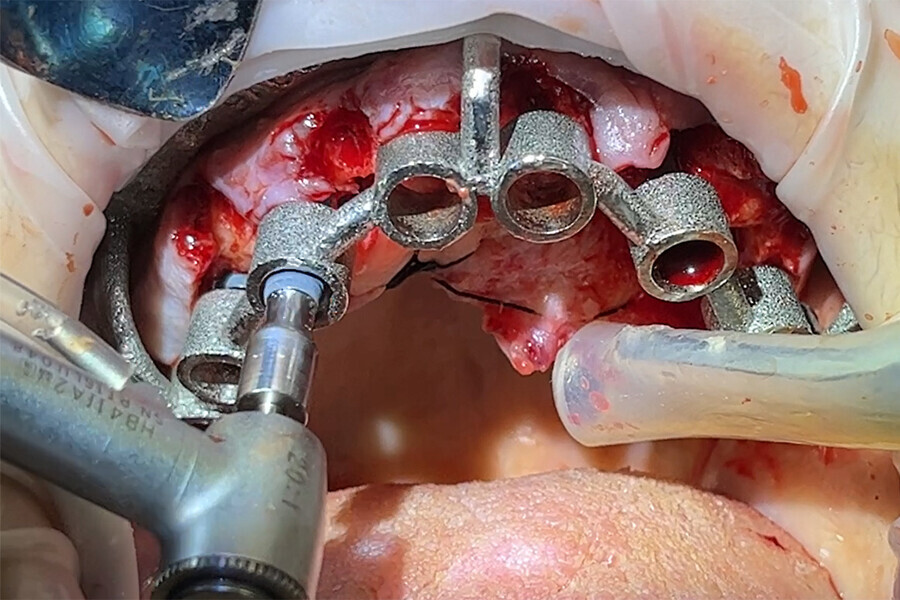
The collected data, along with preliminary plans for potential implant receptor sites (Blue Sky Plan, Blue Sky Bio), was submitted to the laboratory (ROE Dental Laboratory) for review. The 3D data from the CBCT scan was then merged with the IOS data set to aid in determining a restoratively driven solution for both arches. The laboratory then designed provisional full-arch screw-retained restorations utilising CAD software at the designated VDO required for the prostheses. The desired tooth position as visualised with the 3D reconstructed volume of bone helped to determine the most favourable implant receptor sites. A virtual remote planning session was held with the laboratory to finalise the full-template guided surgical plan (CHROME GuidedSMILE, ROE Dental Laboratory), which incorporated a 2 mm increase in the VDO, and the case was sent for production. The CHROME GuidedSMILE protocol consists of several component parts, which provide a stackable solution with metallic scaffolding to control the bone reduction, the preparation of the osteotomies, full-template guidance of the implants into the bone, control of implant depth, trajectory and rotational indexing, the positioning of the MUAs and the delivery of the provisional restorations.1

Fig. 11b: Maxillary intra-oral scan.

Fig. 11b: Maxillary intra-oral scan.

Fig. 11c: Mandibular intra-oral scan.

Fig. 11c: Mandibular intra-oral scan.

Fig. 11b: CBCT scan for diagnosis and treatment planning.

Fig. 11b: CBCT scan for diagnosis and treatment planning.

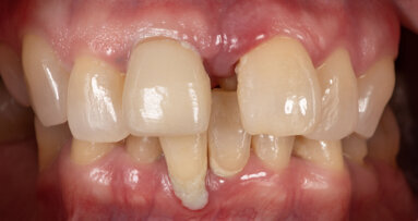
Fig. 11e: Pre-op photograph showing a reverse curve of the mandibular teeth and poor aesthetics.

Fig. 11e: Pre-op photograph showing a reverse curve of the mandibular teeth and poor aesthetics.

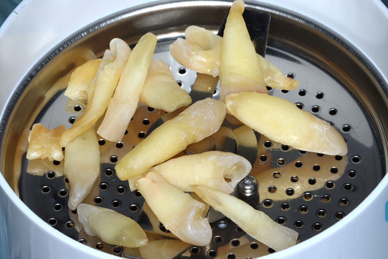
The surgery for both arches was completed in a single visit under intravenous sedation. All the remaining teeth were extracted, and selected teeth were then pulverised utilising the Smart Dentin Grinder (KometaBio) and sterilised to be used as autografting bone substitute2 (Fig. 12).

Fig. 12a: Using extracted teeth to achieve autologous bone substitute using the Smart Dentin Grinder.

Fig. 12a: Using extracted teeth to achieve autologous bone substitute using the Smart Dentin Grinder.

Fig. 12b: Using extracted teeth to achieve autologous bone substitute using the Smart Dentin Grinder.

Fig. 12b: Using extracted teeth to achieve autologous bone substitute using the Smart Dentin Grinder.

Fig. 12c: Using extracted teeth to achieve autologous bone substitute using the Smart Dentin Grinder.

Fig. 12c: Using extracted teeth to achieve autologous bone substitute using the Smart Dentin Grinder.

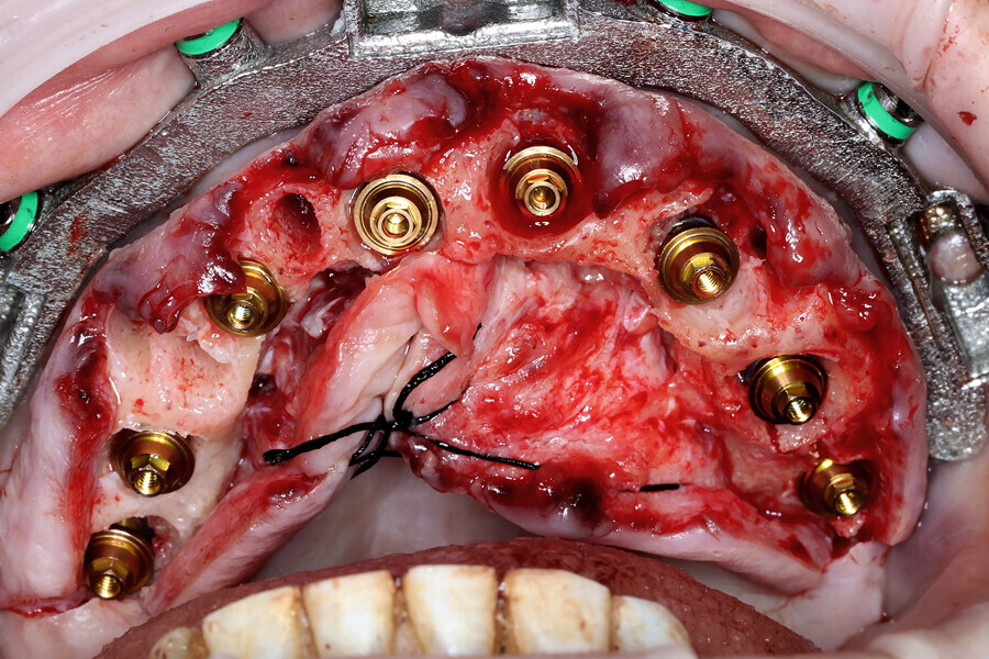
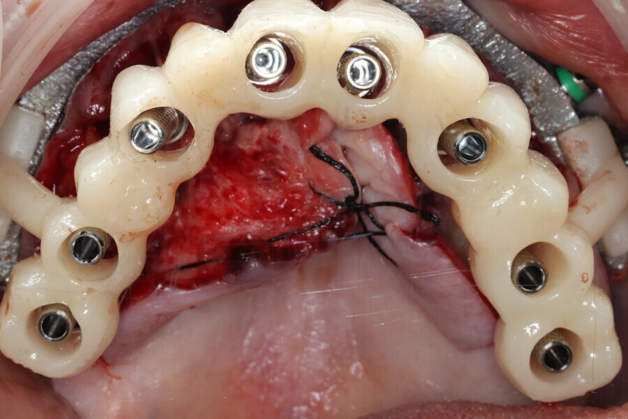
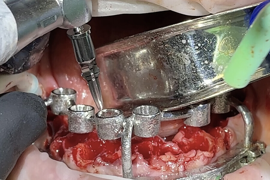
A biologically driven drilling system for anatomical alveolar sculpting (Universal Shapers) was employed (Fig. 13). The alveolar bone was scalloped utilising the diamond shaper drills for both implant and pontic sites to promote emergence profiles for enhanced aesthetics according to the basic tooth size requirements assessed from the initial data collection. The surgery was uneventful except for a mild complication during the extraction of the impacted mandibular canine. Implant stability was measured with resonance frequency analysis (implant stability quotient) to validate loading. MUAs were secured to each implant based on the rotational positions predetermined by the surgical planning. Deficient sites and residual tooth sockets were then grafted with the ground dentine autograft, covered with platelet-rich fibrin membranes and sutured around the healing abutments. Provisional restorations were fabricated using the C2F protocol (Figs. 14a & b).4 After customisation and polishing, the provisional restorations were inserted and allowed to heal (Fig. 14c–e).

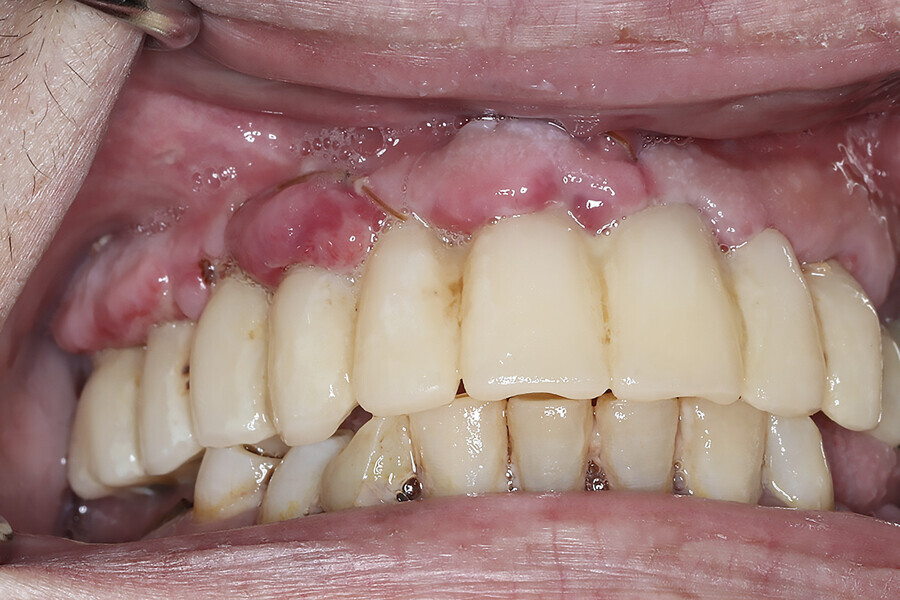
During the subsequent postoperative visits, the patient described being extremely happy with his newly rehabilitated mouth. As the preliminary provisional restorations had been designed based on the desired virtual result, it was possible to make changes as necessary for the final restorations. A slight discrepancy was observed in initial tooth size and midline position, and this was noted in order to be corrected during finalisation of the monolithic zirconia restorations. The patient tolerated the 2 mm increase in VDO, and minimal adjustments to the occlusion were accomplished through digital articulation (OccluSense, Bausch). Tissue healing was unremarkable apart from minor loss in alveolar height and soft tissue in the impacted canine extraction site.

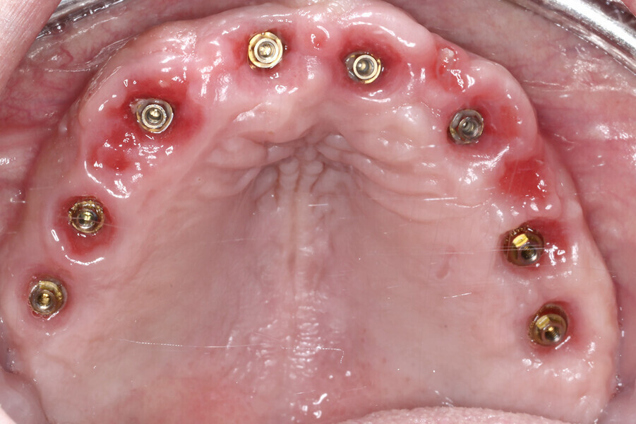
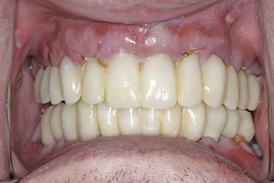
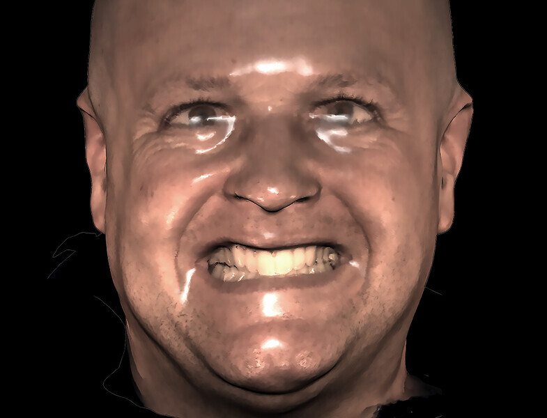
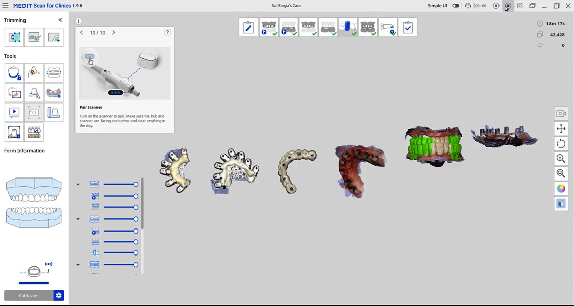
After four months, the patient returned to complete the process of finalising the final prostheses. Final records were taken, including new digital scans and photographs. Photographs included the patient profile when smiling and not smiling as well as intra-oral occlusion. The digital scans included a facial scan acquired from the CBCT device, maxillary and mandibular soft-tissue scans using scan bodies (DESS), bite registration, an iJIG scan of the provisional restorations for tooth positions,3 photogrammetry (iCam4D, iMetric 4D) and Grammetry scans (Fig. 15). The Grammetry scans were scanned extra-orally with both the intra-oral scanner and an extra-oral desktop scanner (Medit T710) for comparison.

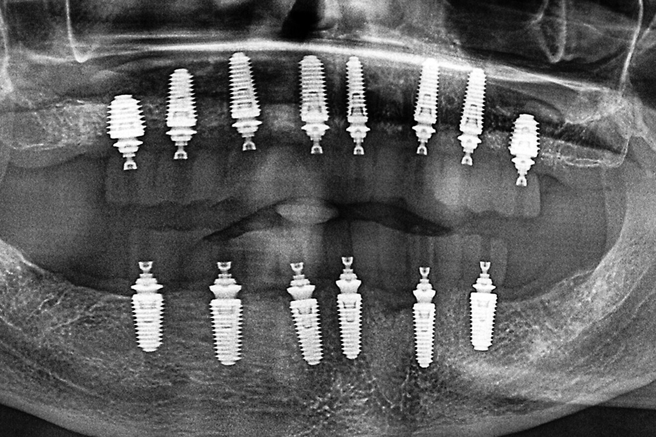
Fig. 16a: Panoramic radiograph showing printed restorations secured with Grammetry Vortex LA VIS screws.

Fig. 16a: Panoramic radiograph showing printed restorations secured with Grammetry Vortex LA VIS screws.

Fig. 16b: Retracted intra-oral view.

Fig. 16b: Retracted intra-oral view.

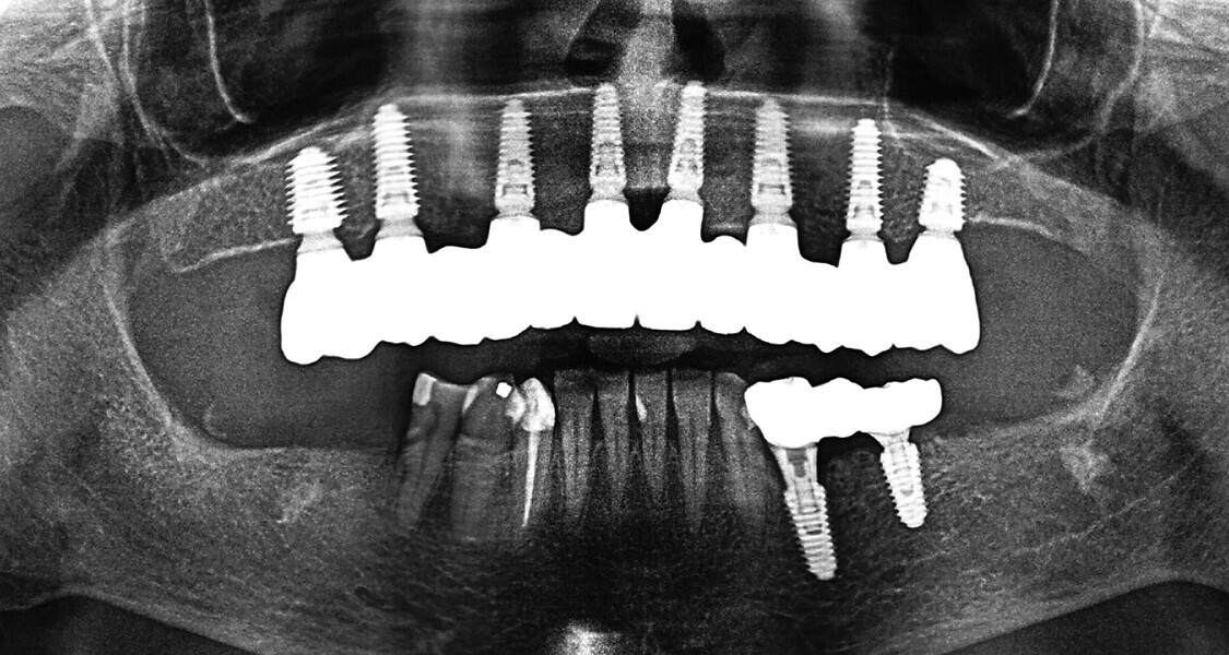
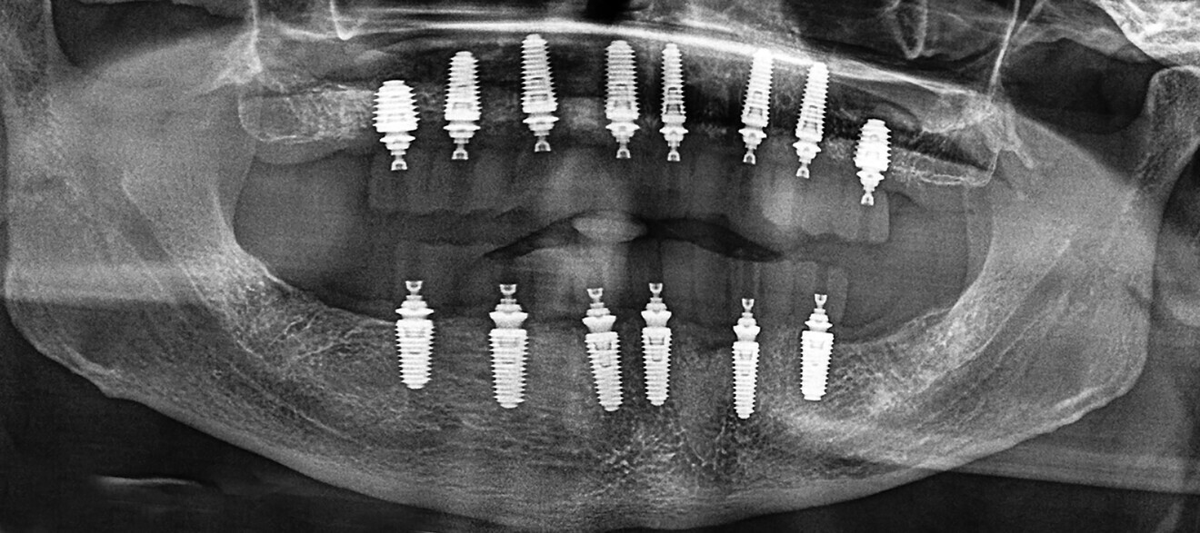
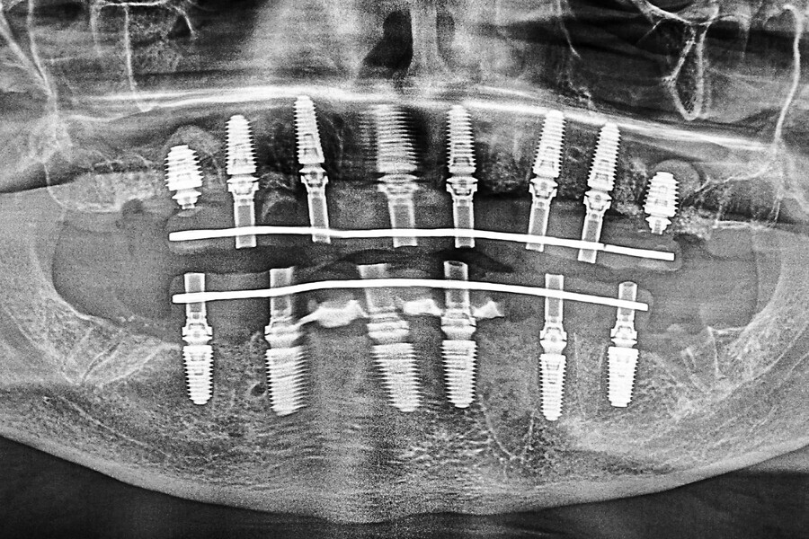
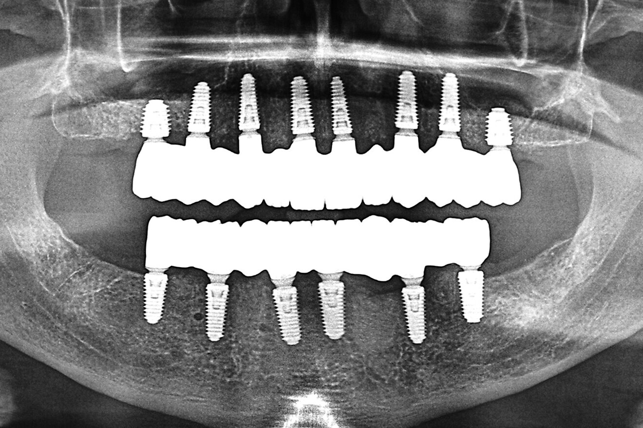
Fig. 17a: Final panoramic radiograph confirming seating of the zirconia restorations.

Fig. 17a: Final panoramic radiograph confirming seating of the zirconia restorations.

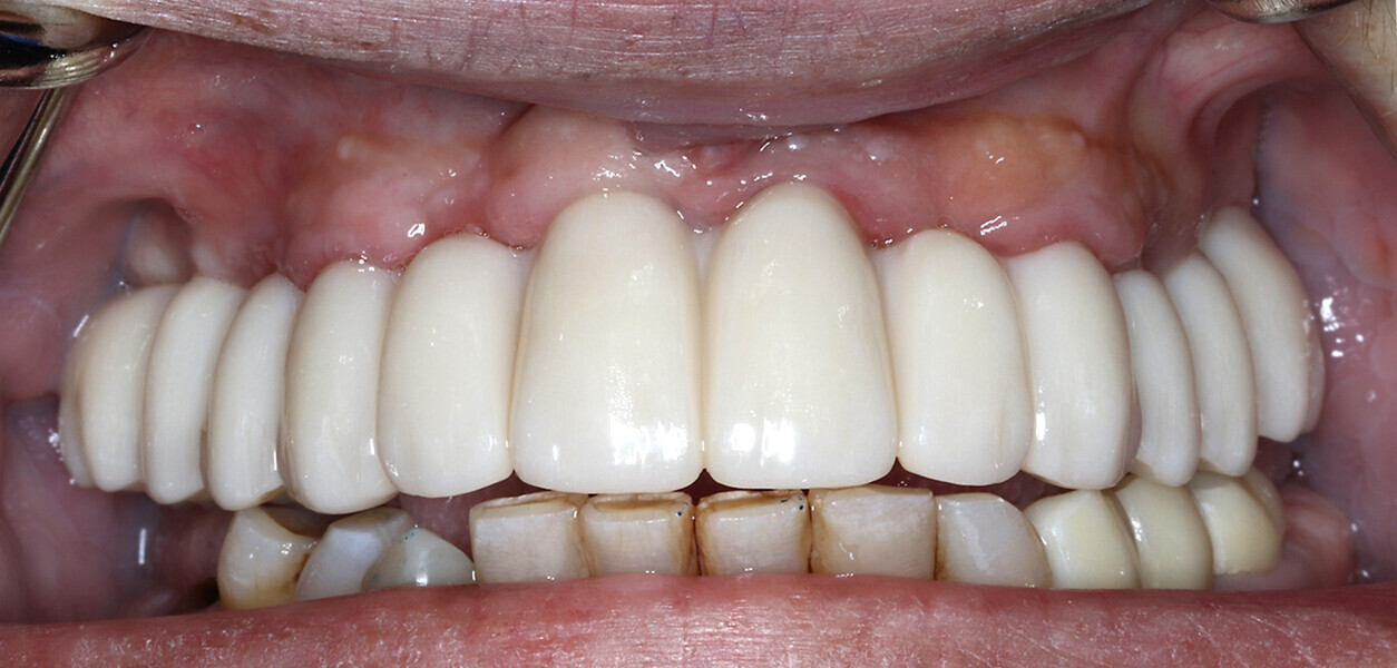
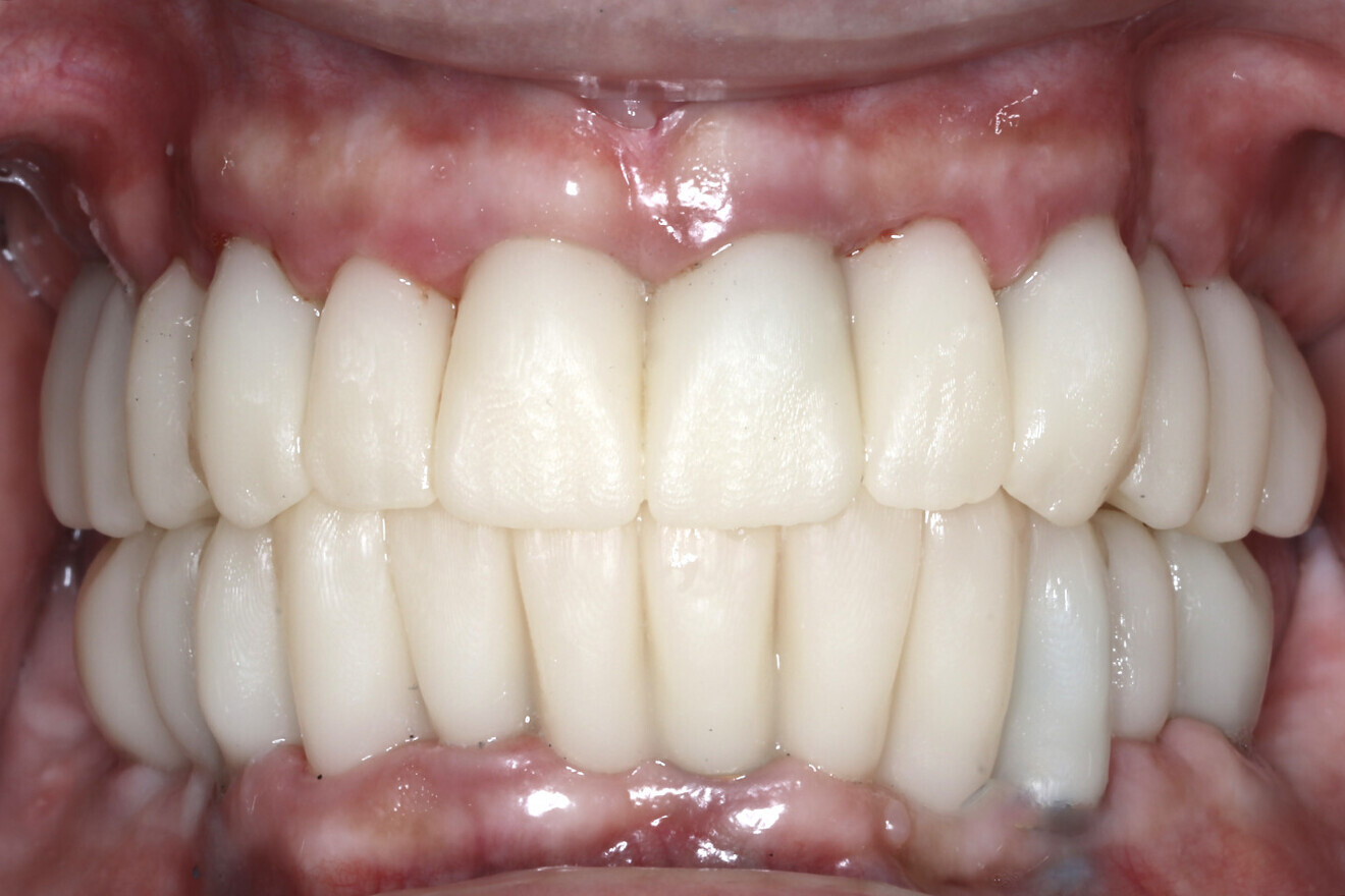
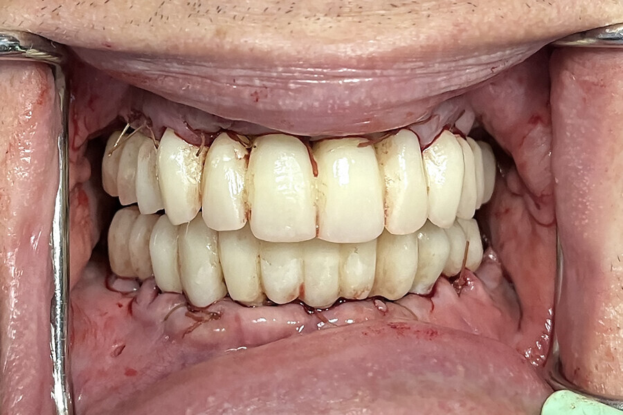
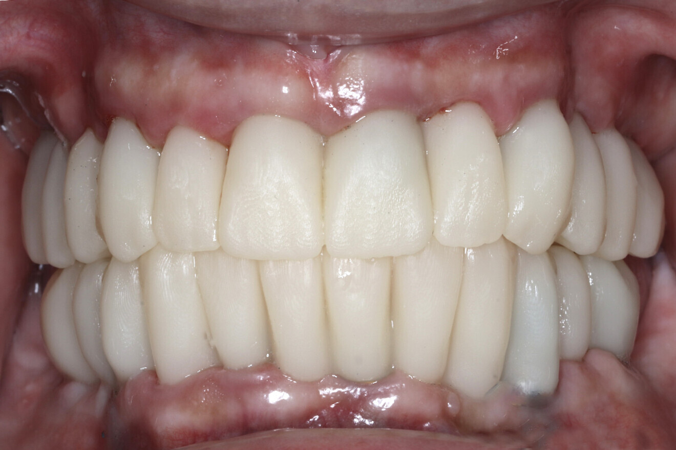
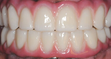
Fig. 17b: Retracted intra-oral view.

Fig. 17b: Retracted intra-oral view.

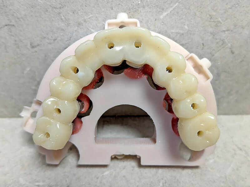
The data collected was sent through a scanning software portal (Medit Scan for Clinics) to the dental laboratory with requested changes for correction of the desired smile design. Utilising advanced planning features in the design software (exocad), the midline and tooth size changes were corrected. 3D-printed maxillary and mandibular PMMA restorations were used for try-in using the direct-to-MUA screws (Vortex LA VIS; Fig. 16a). Fit, phonetics, aesthetics and occlusion were evaluated and confirmed using digital articulation (OccluSense; Fig. 16b). The patient was extremely satisfied with the printed try-ins. Since no adjustments were required, the patient was allowed to leave with the printed try-ins as new provisional restorations made from extra-strong resin. The new provisional restorations were worn for ten days to confirm form and function. The final shade was chosen, and metal-free monolithic zirconia restorations were then fabricated by the laboratory.

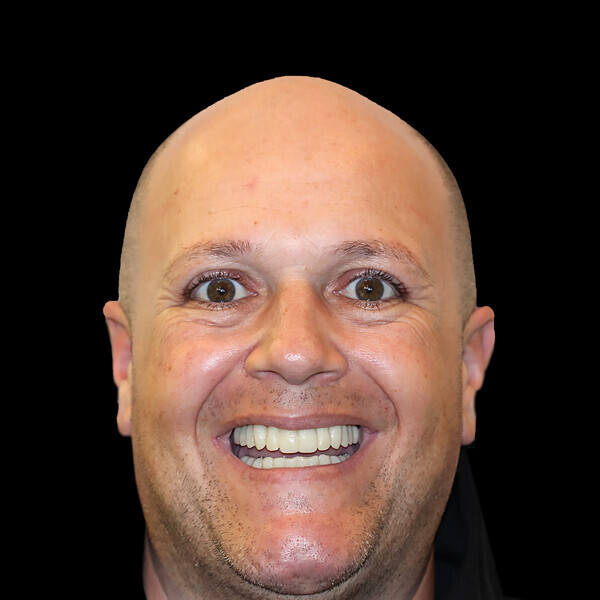
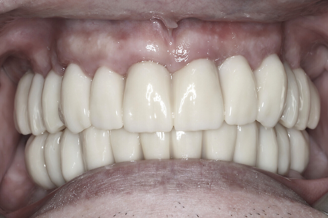
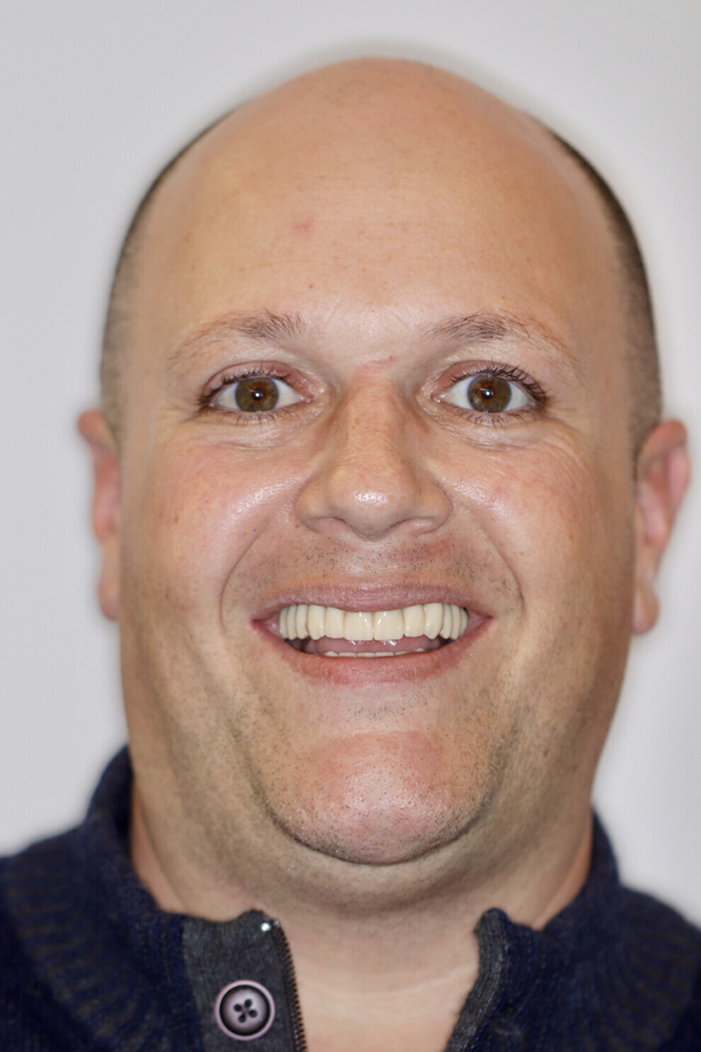
Fig. 17c: Final patient smile showing excellent aesthetics and a happy patient.

Fig. 17c: Final patient smile showing excellent aesthetics and a happy patient.

The final restorations were passively and accurately seated ten days later uneventfully using Vortex LA VIS screws. Confirmation records were taken with photographs, radiographs and digital articulation to recheck fit, function, phonetics and occlusion (Fig. 17a). The patient was extremely satisfied with his final restorations, describing the process as life-changing and surprisingly fast in comparison with what he had heard about full-mouth implant therapy. He was especially pleased with the speed at which the final process was able to be completed (Figs. 17b & c).

Conclusion

With proper diagnosis and treatment planning, single-arch or full-mouth implant reconstruction can be completed in a timely manner under ideal circumstances. The implementation of restoratively driven guided surgery can improve accuracy and ensure proper implant placement, including depth and angulation. Data collection at either the time of surgery or postoperatively can improve the accuracy and speed at which finalisation can be completed.

The present case described digital and analogue protocols for capturing soft-tissue topography as well as the use of iJIG provisional restorations essential to aligning and validating the intra-oral position of restorations, as well as the use of Grammetry and photogrammetry. Voids can be shown with accuracy and adjusted to be filled in using design software. With incorporation of a 2D profile photograph or, better yet, a 3D facial scan, tooth position, size and shape can be easily managed for an improved try-in or final restoration.

In this case, three methods were utilised to capture data to provide a basis of comparison. The first, photogrammetry, has been acknowledged as the gold standard for implant position accuracy. The second, Grammetry, utilised the new OptiSplint analogue luting protocols. The third, digital capture, utilised the Grammetry OptiSplint, in which the intra-oral scanner and extra-oral desktop captures were analysed and compared. The extra-oral desktop capture of the Grammetry OptiSplint was almost identical to the photogrammetry capture when both data sets were superimposed. The extra-oral desktop capture of the Grammetry splint yielded marginally better results than the intra-oral scan captured extra-orally. Although the results may be slightly less accurate due to the human error associated with intra-oral scanners, they were more than acceptable, as CAD/CAM unit tolerances prevent milling beyond the results obtained. An added benefit of using the Grammetry process is the possibility of producing a physical model, allowing for an analogue try-in for producing both printed try-in and final milled restorations.

In summary, there are various existing digital workflows which can be successfully utilised to achieve consistent and accurate results for full-arch implant-supported restorations. Currently, owing to supply chain shortages and limitations, photogrammetry devices are on back order and in short supply. Grammetry protocol components are both available and less expensive. For the purposes of this case presentation, it was found that the analogue–digital protocol of Grammetry can be used as an effective, affordable and equally accurate alternative to photogrammetry. In combination with the necessary records, Grammetry can provide a fully digital capture of implant positions while providing analogue models if desired for articulation and restoration fabrication. Capturing data either on the day of surgery or later on can greatly improve dental laboratory communication and reduce final prosthesis production time while supporting a high level of accuracy, enhancing the overall clinical and patient experience. Future research on the protocols and materials utilised for this case presentation is recommended, as the search for the most economical and accurate digital workflows continues to evolve.

Editorial note:

This article originally appeared in Dentistry Today in May 2023, and an edited version was published in digital—international magazine of digital dentistry vol. 5, issue 1/2024 with permission from Dentistry Today. The complete list of references can be found here.
Topics:
Tags:
To post a reply please login or register
advertisement
advertisement